Workshop Guide to Points and Coil Two Stroke Timing via Dial Gauge
By Steve Cooper, VJMC Editor
Now here’s an interesting thought or two; a Yamaha RD350B two stroke motor running at a constant 7,500 rpm for one hour makes 450,000 revolutions in that sixty minutes. Similarly a Suzuki GT125 running at 9,500 rpm under the same conditions would be spinning the crank around 570,000 times. Obviously in the real world this is unlikely to happen constantly but it puts into perspective just how hard an engine and all of its components actually have to work.
At the top and bottom of its stroke, the piston is momentarily static but at its maximum velocity it can reach speeds of around 4,000 feet per minute. Taking this all into account, the internal combustion engine is a pretty amazing piece of kit. To get the spark to occur at precisely the correct time for each revolution of the crank, we are relying on a switch consisting of two small discs of steel alloy, a couple of lumps of plastic, the odd steel pressing and a hi-tech hair clip.
If you went touring on a Suzuki T500 and cruised at 5,500 rpm for a total of eight hours, then each set of points would have fired each plug 2,640,000 times and on every occasion the spark would have been delivered with precision and accuracy.
To get the maximum potential out of these and similar motors, many parameters have to be correct but probably none is more critical than the point at which the spark occurs. Back in the days of BSA Bantams and James Captains, points were set with cigarette paper and ignition timing was measured with an oily lolly stick or a rusty metal rod onto which a mark was scratched. The point at which the spark fired was normally measured in sixteenths of an inch or thirty seconds, if you were really keen and looking for that last ounce of power. With the advent of small, efficient and precision engineered strokers, the Japanese upped the game and suddenly exact numbers were needed to get the best out the high revving motors.
If a Bantam timing was specified at 1/16” BTDC, (before top dead centre) a lightweight Japanese twin would (for example) be set up at 1.8mm ± 0.05mm. Whilst the low powered strokers could be set up almost by eye, the Japanese machines needed precise measurements and this was normally done using a dial gauge. There were normally no tolerances given on the old low powered shonkers and to all intents and purposes, it made little (if any) difference. Now go back and look at the limits for our Japanese machine at ± 0.05mm. This equates to four thousandths of an inch, or pretty close to the floppiest feeler gauge you own. This means that the spark has to occur within a 'four thou' limit each and every time the piston approaches TDC; tell me you aren’t impressed, I dare you! And the engine runs powerfully and reliably day after day, operating over a wide set of ambient conditions at such fine limits and all without a single damn electronic component. Obviously to get anywhere near all that potential performance, we need to have the spark delivered at exactly the correct point in the engine’s cycle and this is the essence of ignition timing. People often comment that their bike’s timing has slipped; in fact unless you forgot to tighten something up, it won’t. New points often go out of limit as the heel beds into the cam and with age, wear is inevitable. However, armed with some basic knowledge and a few tools we can set up a stroker’s ignition as well as any mechanic.
Here we have the key ingredient to accurately measuring where this critical point occurs via the dial gauge. This is a precision piece of kit and can be thought of as a highly accurate, rotary, vernier gauge. Inside are a series of watch-like cogs that convert linear motion into rotary motion. By a set of gears, the smallest increase in the crank’s angle (and thereby the piston’s height in the cylinder) is converted to a pronounced movement of the dial gauge’s needle. Thus we are able to observe minute changes in the piston’s position relative to TDC as apparent large visual movement.
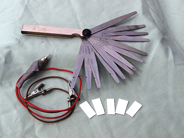
To carry the task in hand we also need a set of rust free feeler gauges; a bulb on a flying lead (with crocodile clips or similar), possibly a power source of six or twelve volts (as appropriate) and some small slivers of plastic for use on multiple points. Add in a spanner that’s a good fit on the end of the crank and we are ready to go.
The same principles apply whether the engine is on the bench or resident in a frame; access is all-important so make sure you can see what you're doing.
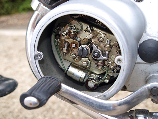
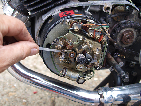
Many machines have a points cover which allows access to the ignition system, but in all honesty it’s often more akin to key hole surgery and there’s a distinct chance of the main case getting in the way of what we’re trying to do.
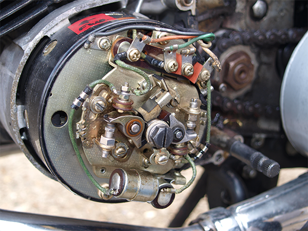
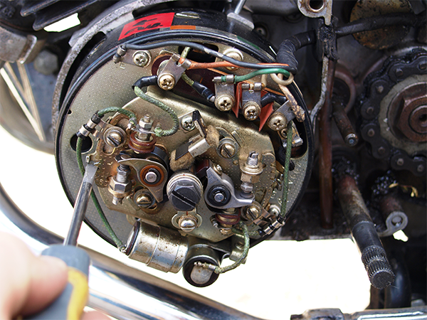
Compare access to the generator and points of this elderly Yamaha, via the points cover, and subsequently with the outer LHS engine cover removed; why would you bother?
Before we get stuck in, it’s worth having a quick look around the exposed workings and make sure all is as it should be. If there’s any signs of oil leakage behind the generator this needs to be addressed before we proceed any further. Likewise, if there’s damage to the loom this needs to sorted, and finally it’s worth checking the length of any carbon brushes on the slip rings or armatures whilst the cover is off; excess carbon from worn brushes can normally be removed either with a gentle blow from an air line, or with some contact cleaner. With the basics checked, it’s now game on for the job in hand.
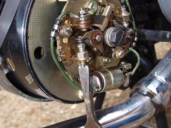
First off we need to examine the points and their general condition. Bottom line here is that there is no justification in messing around with worn, pitted or corroded points; you’re simply wasting your time. For minimal outlay you should be able to find either NOS or good pattern points fairly easily, ditto condensers which may be needed if the current points sets are obviously heavily pitted. As an aside, it’s often possible to buy points either as a standalone pair or a part of a set mounted on a back plate.
Normally, you’ll only need the points themselves. However, if somebody heavy-handed has been in there levering away with a chisel or similar, it’s worth buying points and back plate combined. The notched adjuster and pry peg are almost guaranteed to be butchered and without the peg to lever against, the subtle movements of the points against the back plate will be difficult. On the assumption the points are either okay or brand new, it’s time to set the gap before we go anywhere else. With the spark plugs out, drop the bike in gear and rotate the rear wheel in the normal forward direction to ascertain which way the engine revolves. This may sound obvious, but don’t take anything for granted because when we come to use the dial gauge we need to make sure any back lash is taken out of the system. Furthermore, it’s normally pretty important that the engine is timed at so many millimetres before to dead centre and not after TDC. Please don’t ask me to elucidate on this - it’s an entire Saturday of my life I will never get back! Having established the direction of rotation, the bike can be dropped back into neutral and the engine turned over with a spanner. My personal preference is to use an open ended spanner as this seems to allow a little more flexibility when working but a ring spanner is also fine. Ratchet spanners and sockets are probably more hassle that they are worth here when you need to reverse the direction of rotation. Turning the engine over, we are looking for the largest opening gap on the points, which is where the highest spot on the cam levers the heel of the points to their greatest deflection. Your manual should give a figure in either millimetres or thousandths of an inch and this is the measurement to stick with.
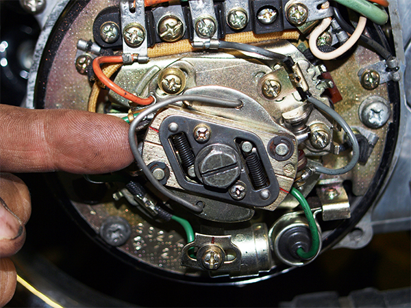
With a clean feeler gauge check the gap and adjust if necessary, remembering that the blade of the gauge should be a gentle sliding fit, not sloppy or overtly tight. If the gap is wrong, slacken off the pinch screw and adjust, reassess and proceed to the next set of points. On the bike pictured, the points are blessed with a screw adjuster to each contact set; this is a luxury and most machines will probably run a more conventional pivot system.
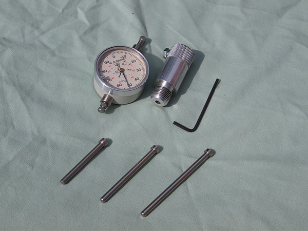
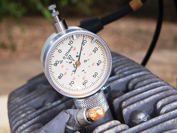
With the points gap(s) set, we now can actually set the ignition timing. The dial gauge I’m using is a multi-purpose unit that requires a threaded adapter that screws in tight to the plug hole. The dial gauge is nipped into place with a grub screw or bolt with a moving plunger inside the combustion chamber. Some degree of manipulation is needed in getting the plunger in exactly the correct position. As we can see in the back in the first picture, the gauge comes with various length adapter rods that can be cut to suit different applications.
I was taught to also add a short length of semi flexible plastic tube to the end of the adapter rod, as this will act as a safety link should you set the unit up wrong or you inadvertently use the wrong length rod; a short length of heat shrink sleeving works fine.
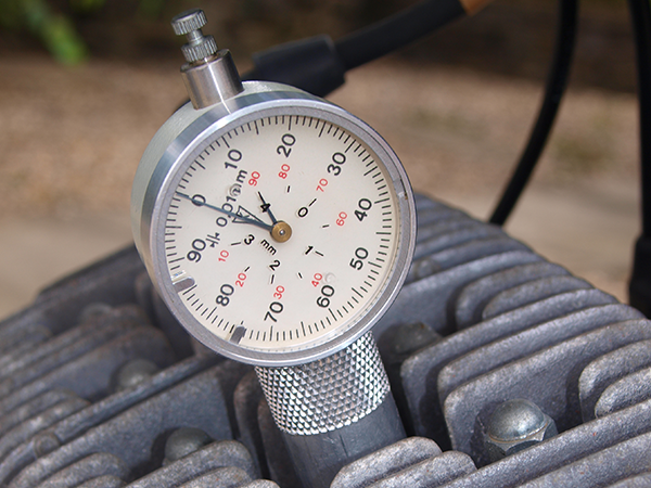
Now is a good time to have a quick play without actually adjusting everything. On my dial gauge, one complete revolution of the big needle equates to one millimetre of vertical piston movement but check your instrument to be sure. By trial and error, find TDC and adjust the outer bezel of the gauge so that TDC is at zero millimetres. I also adjust the two movable pointers on the outside of the dial gauge to the plus and minus limits of 0.05mm around our target setting. On the bike pictured, the spark needs to occur at 1.8mm BTDC which is effectively almost two complete revolutions of the gauge (please note this is dial gauge and NOT crank revolutions) before the piston reaches the top of its stroke. So working from TDC we turn the engine backwards to the normal running direction for three millimetres (or three revolutions of the dial gauge). Now the engine is turned forwards to remove any backlash in the crank, (if we had a bulb across the points) we would see where in this cycle of three millimetres the spark actually occurs. If you’re new to this it’s worth playing around on several dry runs until you are comfortable with what’s going on.
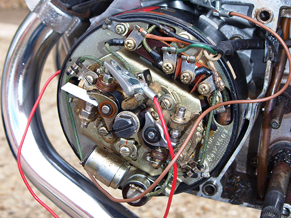
Now back at the points; it’s time to actually measure what is really happening. Power for our test bulb can either be taken from the bike’s own battery or via an external source. If you use the bike’s battery on a multi-cylinder motor, my instructor always recommended either you remove the leads to the sets of points you are not using, or separate them with small piece of plastic. Some bikes can do odd things with back EMFs and this can play havoc with the bulb you are trying to observe. If you are running an external battery, the circuit runs switched side of points to bulb, bulb to battery, battery to frame engine case. Using the bike’s battery, you simply switch on the ignition and connect the bulb across the switched side of the points to earth. With our dial gauge in place as previously described and our points (which are really only a timed on/off switch) powered up, we rotate the engine back three turns of the gauge and then slowly back to our 1.8mm specified point.
If we’re lucky the bulb will either illuminate or go out (depending on our power source) at 1.8 ± 0.05mm, but if not we need to adjust the position of the points relative to the tip of the cam and thereby the crank and pistons. Please note, the large needle of the dial gauge is pointing to 1.2mm; this equates to 1.2mm from our nominal 3mm starting position or 1.8 mm BTDC. So we slacken off one back plate screw for a full turn and the other just slightly to allow controlled adjustment of the back plate.
Using the notched adjuster and pry peg, the back plate can be moved gently in either direction, the screws nipped up and the timing rechecked. Initially this process may be somewhat frustrating as it’s very easy to move the back plate too far and either end up with 4mm BTDC or 3mm ATDC. Bear in mind that you are effectively moving the points over a parabolic surface or progressively changing radius. As the points heel gets closer to the apex of the cam, the amount of movement needed to effect a small change decreases disproportionately. With a bit of effort it should be possible to zero in on the desired value and then the screws can be fully tightened.
If you find that the back plate needs to be turned to its limit in either direction, try reducing or increasing the points gap on the relevant set of contact breakers by 'one thou', which should bring the adjustment somewhere near the middle of the range. Each subsequent set of points and cylinder is normally set up in a similar manner.
Modern electronics have pretty much killed off points and coil ignition and fitting an aftermarket black box kit is probably a good idea if your bike is ridden regularly. The benefits are fit-and-forget, along with potentially better starting, smoother idle and less vibration. However, to fit such units you still need to know how to set up the ignition timing. They aren’t exactly cheap and in purely fiscal terms if you have a garage full of bikes, such conversions could very easily spin into four figures for a small fleet. In many cases the kits are generally only made for the more popular models, so if you ride something outside the mainstream, you’re still going to need that dial gauge. It’s not a black art honestly; for many years timing was my own personal bete noire, but the monster has been now been slain and my strokers sing. Invest in a dial gauge, set some time aside and make a point to your mates.
Exceptions, conundrums, alternatives and the downright weird
On many points and coil systems you’ll notice a felt pad that rubs against the cam; this device is intended to act as a lubricator. There’s some debate as to the efficacy of these little chaps but I’m firmly in favour of giving them the benefit of the doubt. A few drops of light machine oil will hopefully give the heel of the points and the cam an easier life. The screws used in Japanese ignition systems are no different to those used on the outer engine cases, are easily damaged and in need of replacement. In principle there’s nothing wrong with using easily obtained cap head or Allen screws but make sure to use a washer under each so that the bottom of the socket head pulls down squarely and not into the fixing hole. If you do opt for this mod, remember you can get a lot of leverage on a hex key so please do not over-tighten. Some bikes will have a master set of points that need to be set up first. Refer to the manual or get input from an owners club if you are in any doubt.
If you time a bare engine on the bench bike, (with an external battery) it’s normal for the bulb to go out as the points close and not burst into life. In all honesty, it doesn’t really matter which way you get to the point of contact/separation as long as the method is consistent. Back in the day, many dealers used buzz boxes instead of bulbs and these little black boxes are still very useful.
Powered by a PP9 battery, the box emits a constant tone that changes as the points begin to open. Normally when the buzzer reaches its highest tone is the moment at which the points have opened. This system is very useful as you can keep both eyes on the dial gauge and use your ears to find out what’s happening, rather than having to keep one eye on the pointer and on the bulb.
It’s also possible to use a multimeter set of Ohms in place of either the bulb or buzzer, but frankly, the digital displays of modern meters all move too quickly for this old codger and I’d rather keep an eye on a bulb, than have to balance a multimeter off a petrol tank somewhere within my line of sight.
To add spice to our lives, some strokers have an advance/retard mechanism (Yamaha CS series spring to mind) and the unit normally needs to be held open or the measurements will be woefully inaccurate.
A short length of bent coat hanger normally does the trick but make sure it stays in place and doesn't get caught in the points or their associated wiring. Some manufacturers really went cheapskate when they built their bikes; there are a few that have one set of points on a back plate and the others are fixed directly to the generator. The moveable breakers are set up first and, if all is well, the second set is simply gapped to give the correct timing. If the gap is beyond the limits specified, the manuals tell you to buy a new set of points!
For more technical advice, visit Motorcycle Workshop Guides: The Complete List.
To find out more about a classic bike policy from Footman James and to get to an instant quote online, visit our Classic Bike Insurance page.
The information contained in this blog post is based on sources that we believe are reliable and should be understood as general information only. It is not intended to be taken as advice with respect to any specific or individual situation and cannot be relied upon as such.

COMMENT