Workshop Guide to Swinging Arm Bearings
by VJMC Editor, Steve Cooper
This man's life has been temporarily blighted by Satan’s Suzuki, or to be more truthful, my mate Ian’s X7. This ongoing project had been the subject of a partial parental rebuild but has now been moved on from father to son as an ongoing project. Now in running condition and with an MOT (although God knows how) the bike is being fettled back as close to standard as possible without going overboard. Looking at the machine it would seem to be a case of one careful owner and a dozen who couldn’t give a damn.
Having been roped in to have a quick fettle with the carbs following Ian’s first attempt at a largely successful refurbishment, we took the opportunity to have a look at the chassis to prioritise what to do next. A brief once around the bike revealed the worrying absence of a chain guard, but the pillion pegs still attached to the bike. As this should have been an MOT failure, alarm bells started to quietly ring.
Initial assessment of the wheels suggested nothing to worrying at the front end, but a fair degree of movement at the rear. Further investigation revealed the wheel bearings to be fine but a disturbing amount of movement at the swinging arm. Oh dear, an unforeseen expenditure and another step up the restoration learning curve for my mate. They say it’s an ill wind that blows no one any good and at least we were able to document the process, learn how some people take chances with their safety and pass the information on to fellow enthusiasts.
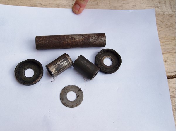
Swinging arm bearings making ominous noises are often accompanied by seized bolts, rusted nuts and spindles corrosion welded to spacers etc. On this occasion, everything came apart with minimal drama and a surprising amount of what looked like fresh grease. According to the X7 parts book, there should be a centre spacer, two needle roller bearings, two bearing tubes, two thrust washers and a pair of lipped metal seals.
The swinging arm spindle was a little dull, but free from significant corrosion and the centre spacer was only rusty on the outside. However, the rest of the parts tell a more worrying story. There’s only one thrust washer (which may account for the movement on the shaft) the lipped metal end seals are bent, distorted and have missing edges and the bearing tubes are frankly toast. Looks like we may have found the source of the problem then.
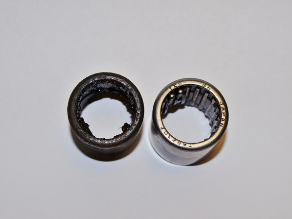
With a little bit of persuasion, the bearings are evicted from their housings and the evidence is frankly scary. The left-hand bearing seems to be all grease and no rollers; in fact, the rollers are still there but reduced in diameter by some 50%. The right-hand bearing is a little better but the needles are starting to fall out of the cage which is hardly ideal. A call to Crooks Suzuki sees all the relevant parts arrive in double quick time and it’s easy to spot the good bearing from the bad. A look at the new parts shows just how much attrition the old parts have experienced and when you look at the bearing tubes it beggars belief that someone really did bother to put the swinging arm back together with such obviously worn parts.
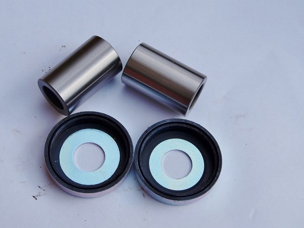
The needle roller bearings are caged and sit in a metal shell that fits snugly into a machined register in the swinging arm. These bearings (sometimes called Torrington bearings) need to be fitted with a fair degree of care to ensure they aren’t distorted, thus rendering them useless. Various techniques are available and the options are either to draw the bearing into the housing with a draw bolt, press it in with a fly press or a wide-jawed vice.
Whichever option is chosen, its good engineering practice to protect the end of the bearing with something that will prevent damage. As we have access to a fly press a copper mandrel has been run up on a lathe. The shoulder has been machined to fit snugly inside the rollers and the face of the mandrel is square to both the outer face of the bearing and the swinging arm. If we were using a draw bolt the mandrel would have a central hole through it and a captive nut on a threaded shaft through the mandrel to pull against.
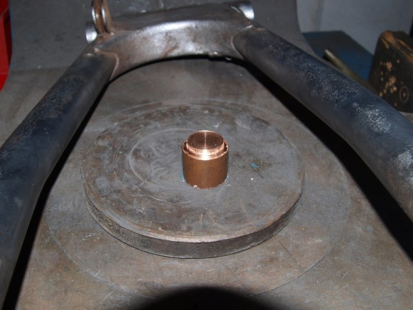
With the swinging arm perpendicular to the press and supported firmly from underneath, the greased bearings are pushed into place. Care needs to be taken to ensure that the bearing goes in true and not at an angle. The metal shell of the bearing is quite thin and can be easily distorted. If the bearing feels like it will be tighter than expected fit, it’s possible to speed its fitting via the application of some crafty thermal management.
Warming the bearing housing will cause it to expand and thus reduce the stresses applied to the bearing and its cage. Ideally, a hot air gun should be played over the surface but if this has good paint then there’s an obvious risk of damage. If this is the case, warming the housing with a hair dryer for 15-30 minutes is often enough to increase the clearance by that vital thousandth of an inch. At the same time, the bearing can be chilled for twenty-four hours in a freezer which will reduce its size. The two techniques can be used in conjunction to fit most bearings in similar situations.
However, on this occasion, we don’t seem to have any problems and the bearings press in without to much hassle. Knowing when to stop applying pressure or winding up the draw bolt is also key to preventing distortion of the bearing, and owner Ian has taken the precaution of measuring the length of the bearing (28mm) and the depth of the housing (29mm).
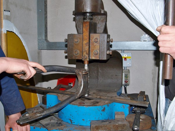
We’re almost there but there’s a millimetre or so of bearing protruding above the face of the swinging arm so another session on the press is needed. Finally, we have our bearing perfectly seated and all we need to do now is repeat the procedure on the other side. With both bearings fully home the new thrust washers can be greased, likewise, the lipped metal end seals and the whole unit can be reinstalled.
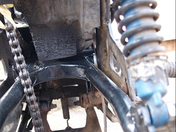
Well, that should have been the end of the job but despite our best intentions the swinging arm doesn’t fit in the frame. After an hour of serious head scratching it’s obvious that the only way it’ll fit is minus one thrust washer which is pretty much where we came into the job. After a cogitative cuppa, the conclusion is reached that the centre spacer is too long and a friendly neighbour machines a fraction less than 1mm off the end of the spacer. The unit then simply slides into place as it should.
If there’s a moral here it has to be that you should never trust an unknown quantity. Even an MOT is no guarantee of a bike’s condition. Why anyone would ever choose to fit an obviously oversized (or pattern?) spacer that necessitates the removal of a key component and reuse totally shot bearings is beyond comprehension but it happens. Caveat emptor as they say. As I’m packing up to ride home we notice the stud mount for the left-hand shock absorber is pretty much devoid of a thread. Oh whoopee doo; looks like we have another job on our hands with Satan’s Suzuki.
For more technical advice, visit Motorcycle Workshop Guides: The Complete List.
To find out more about a classic bike policy from Footman James and to get to an instant quote online, visit our Classic Bike Insurance page.
The information contained in this blog post is based on sources that we believe are reliable and should be understood as general information only. It is not intended to be taken as advice with respect to any specific or individual situation and cannot be relied upon as such.

COMMENT