Workshop Guide to bulb holders
By Steve Cooper, VJMC Editor
On the final lap of my egregious Suzuki Stinger, I’d been fitting the sub harnesses that goes to the clocks with new connectors and sleeving… as you do. The wires to one clock all checked out fine but with the second unit, I had five wires and five no-shows from the continuity meter. First thought was ‘bulbs’, but even when changed, not one of the leads would give me a decent reading. Putting that little lot aside, I naively thought I’d sort out the rear light with a new bulb… which promptly cracked the brown bulb terminal connector of the holder in half, oh joy unbounded! When a replacement, three wire, tail light loom popped up on eBay at $79.99 plus $25 shipping, I decided it was time to get back on the tools. Now pretty much immune to the Stinger’s hissy fits, I got out the appropriate kit to investigate, analyse and repair. Well, I mean, how difficult can it be to sort out bulb holders?
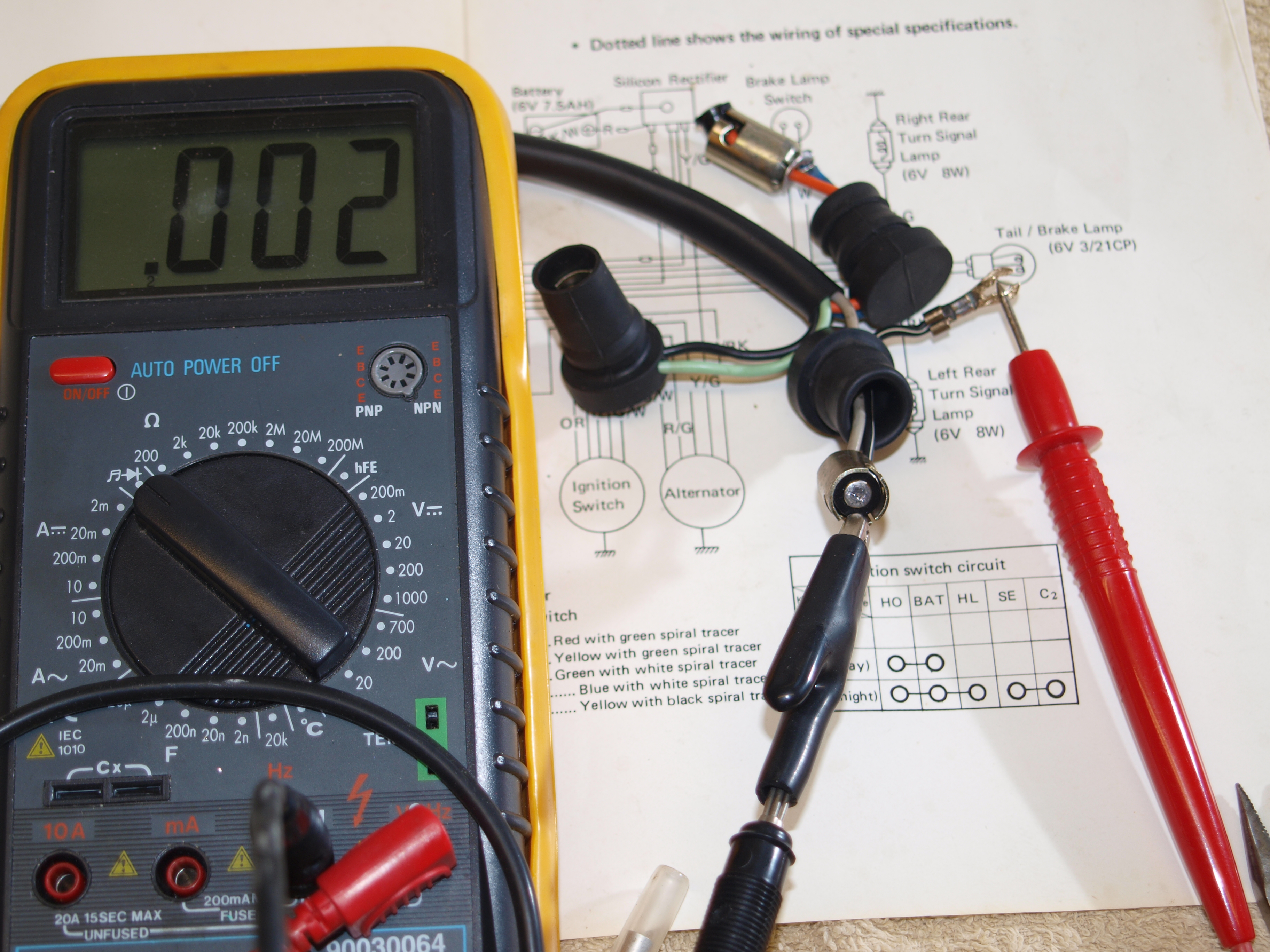
An easy win this one, the earth for the clock housing connects via a split ring terminal that runs a soldered joint for enhanced continuity. Confirmed by an authoritative wiggle of the wire, the joint got re-soldered.
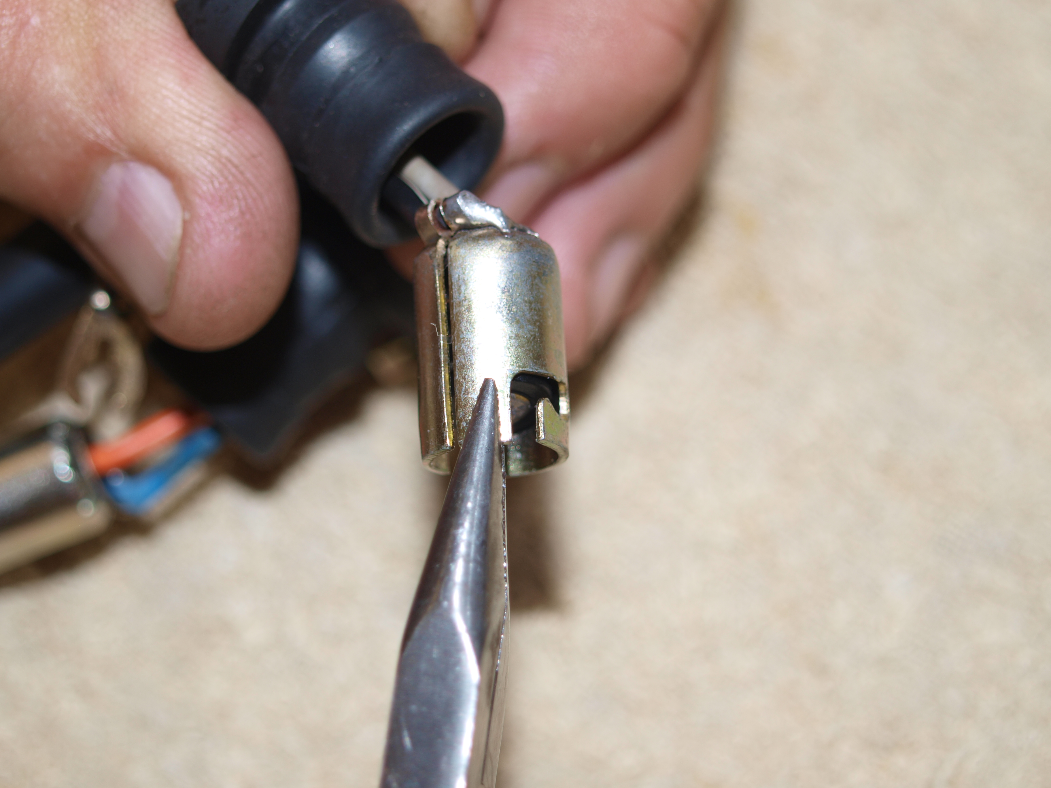
No such luck with the rest sadly, so the idiot light bulb holders are ‘winkled’ out of their rubber sockets with a pair of pliers.
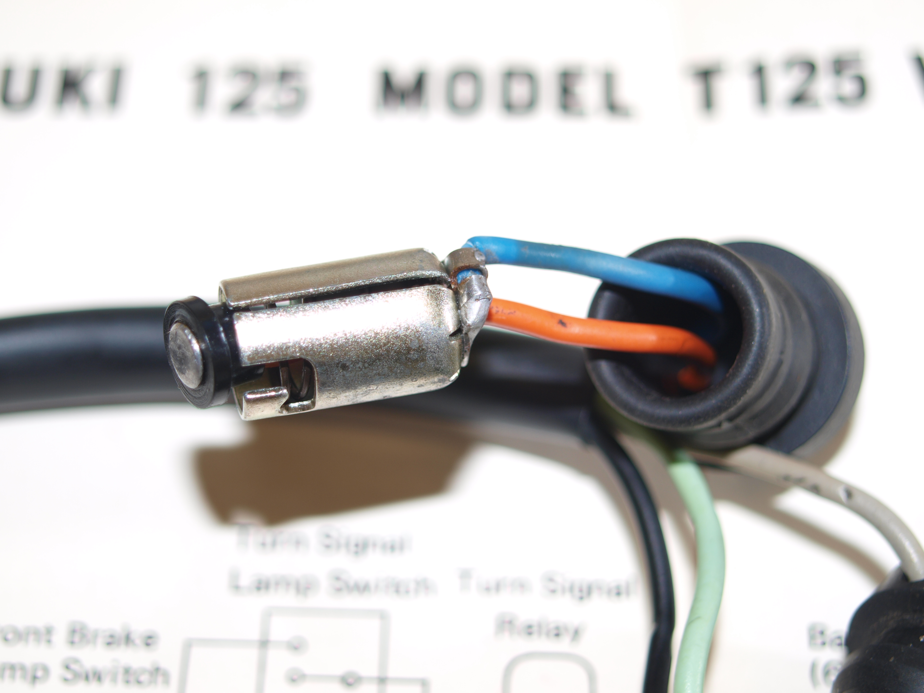
Inside is a very simple pair of connections. One to the outer as the earth and the second to the base of the bulb via an insulated plastic ferrule. Note both joints are soldered to get the best out of the 6 volt system.
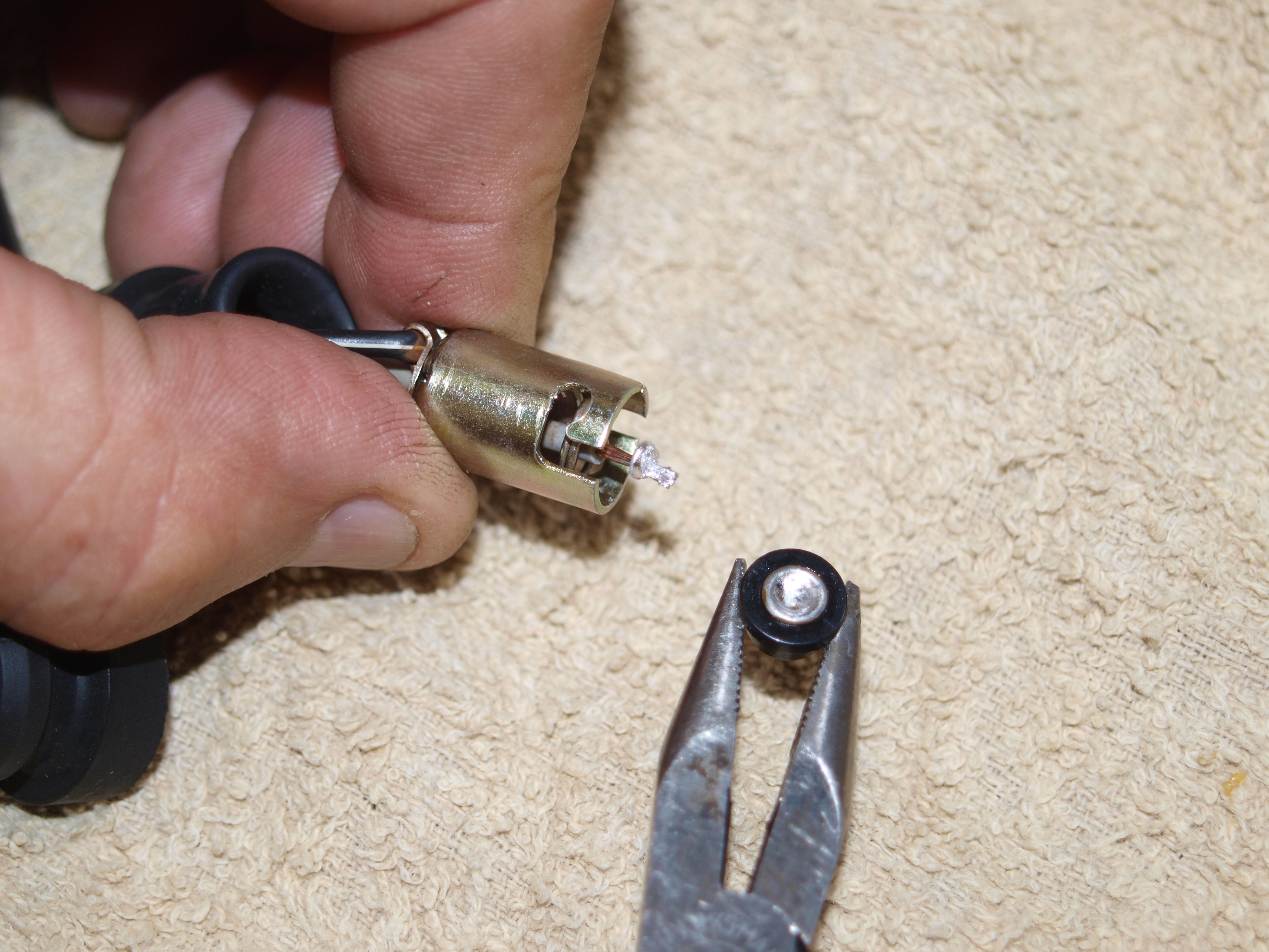
More wire wiggling reveals that one issue is dry joints where the solder has failed over time. The ferrule joint is taken apart carefully with a soldering iron and pair of pliers.
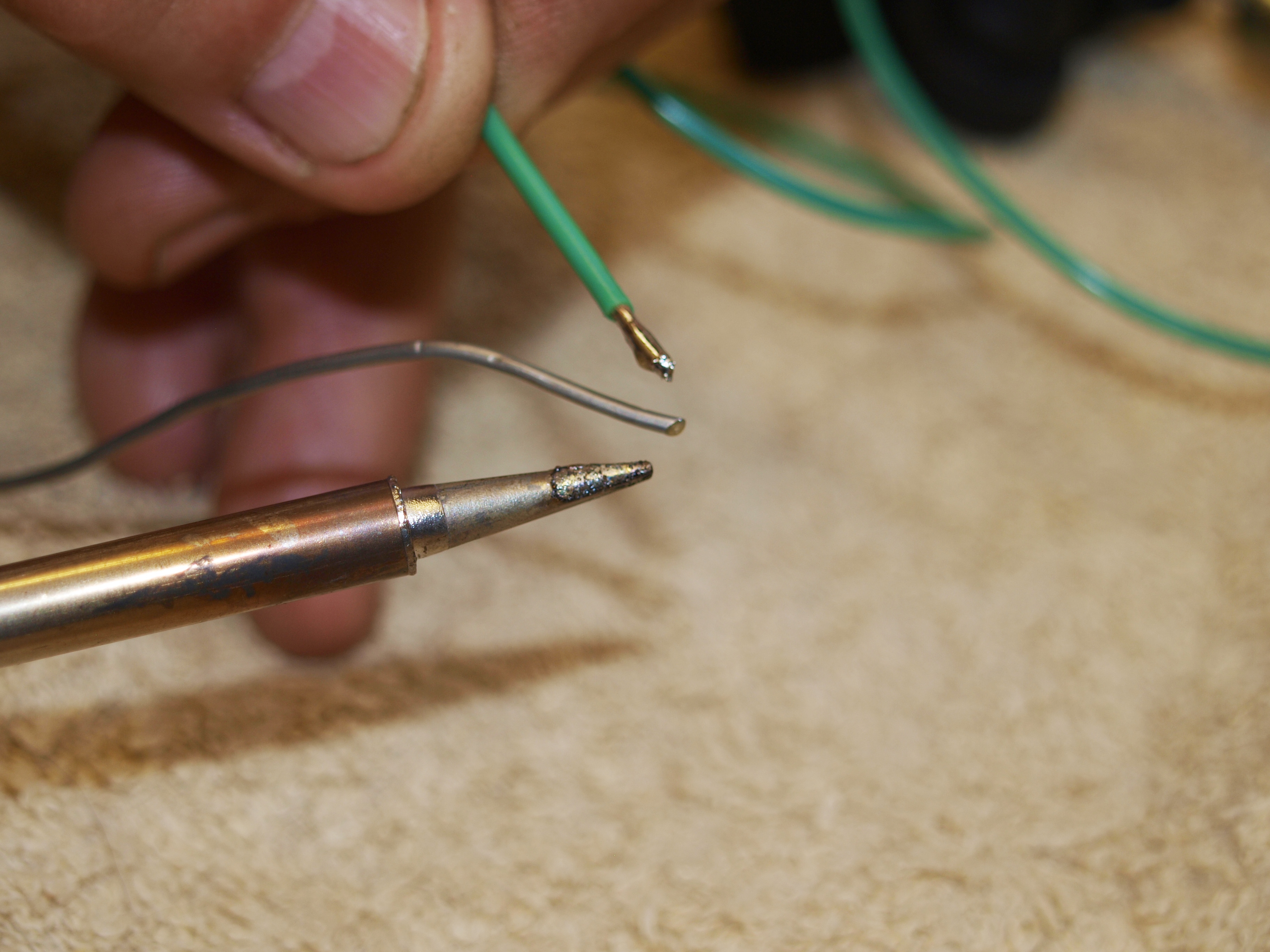
As I subsequently find broken or damaged wires, I’ve elected to remake the sub loom. First off the relevant ends of the wires are tinned with electrical solder.
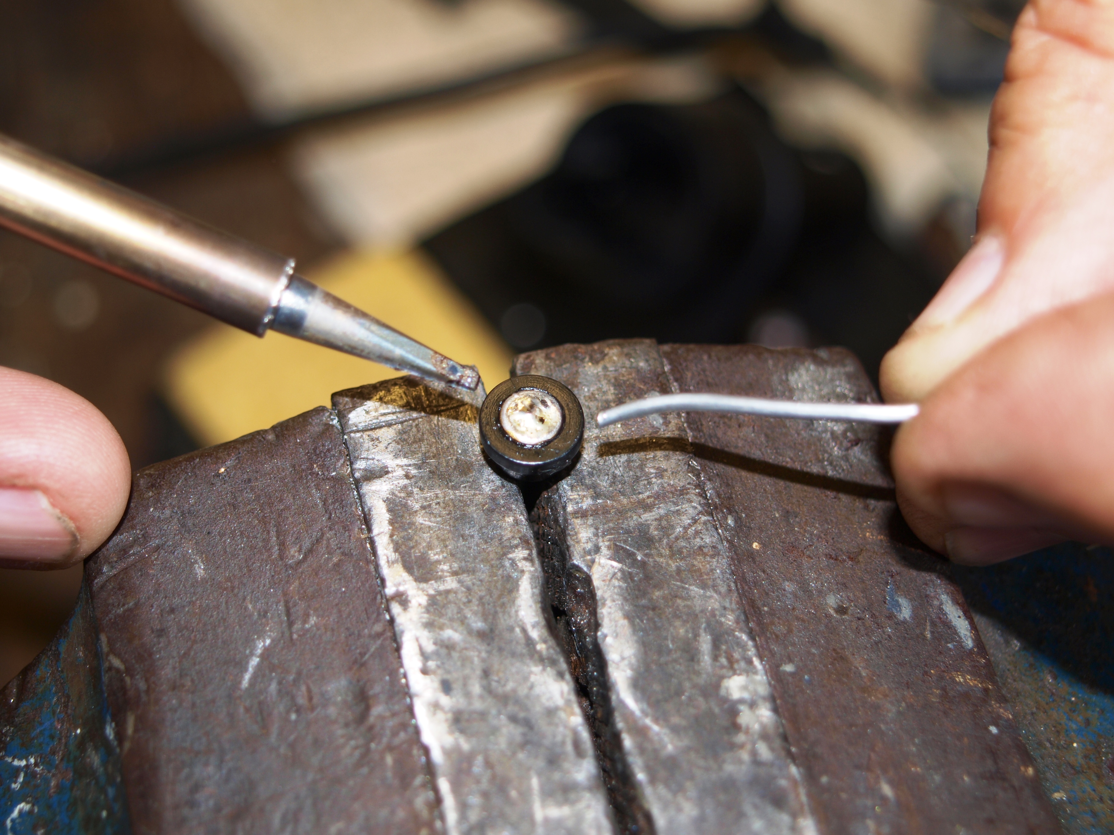
The tinned end of the wire is then fed into the ferrule terminal and swiftly soldered. Inside the black plastic is the thinnest tube of crimped-in brass so it’s imperative only minimal heat is used or the plastic will simply melt.
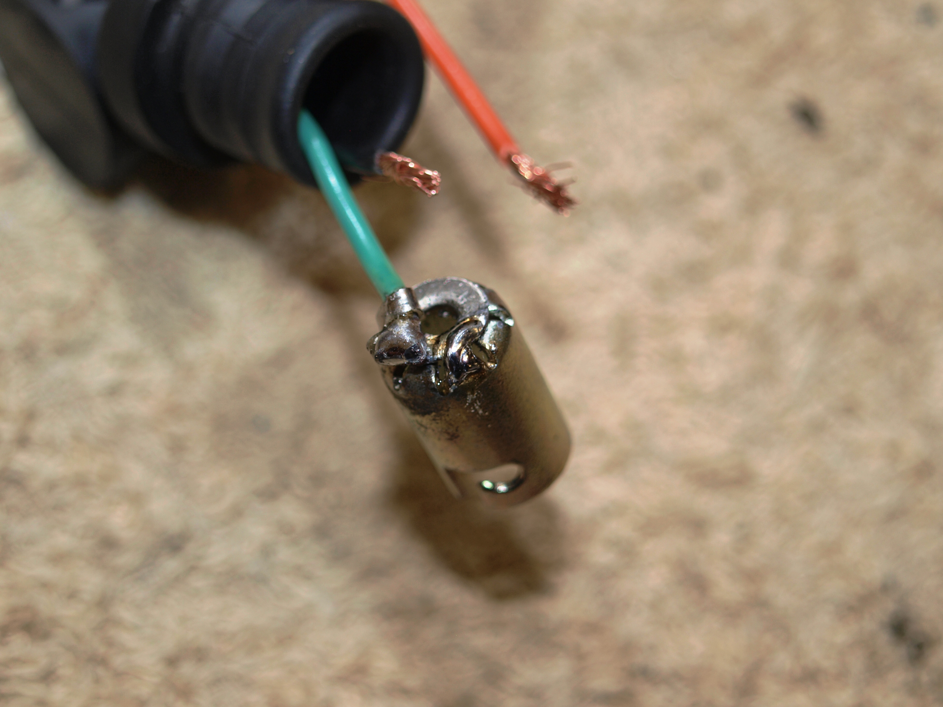
The other continuity problem with the bulb holders turns out to be an earthing issue. The bulb holder is supposed to engage via cleats to a stepped washer which in turn has an earth wire soldered to it. Vibration has destroyed the cleat/stepped washer joint so it’s repaired with a goodly dollop of solder.
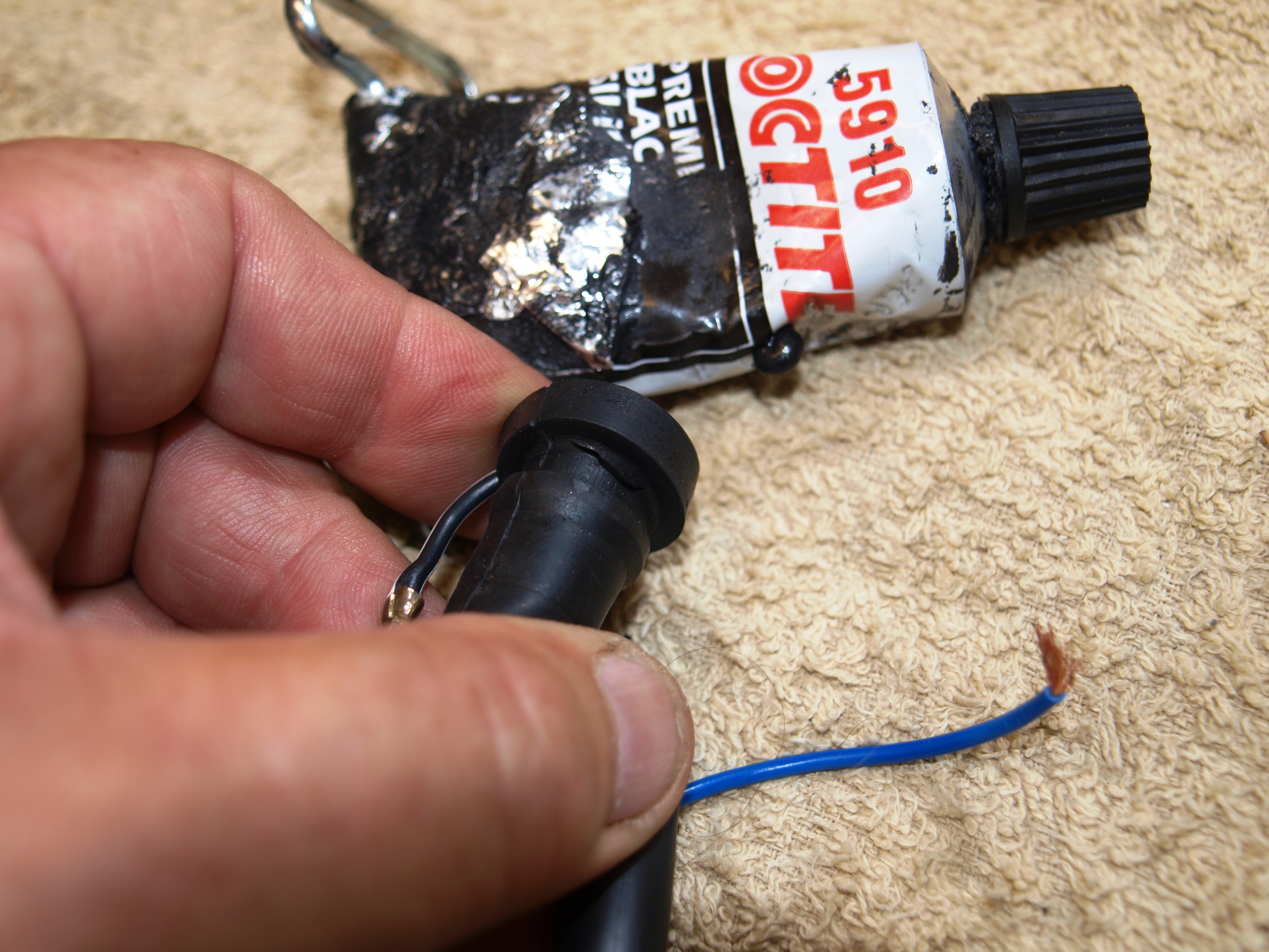
Finally on the clock bulb holders; splits or fissures are carefully repaired with a high quality black silicone adhesive such as Loctite 5910 before new connectors are attached to the wires.
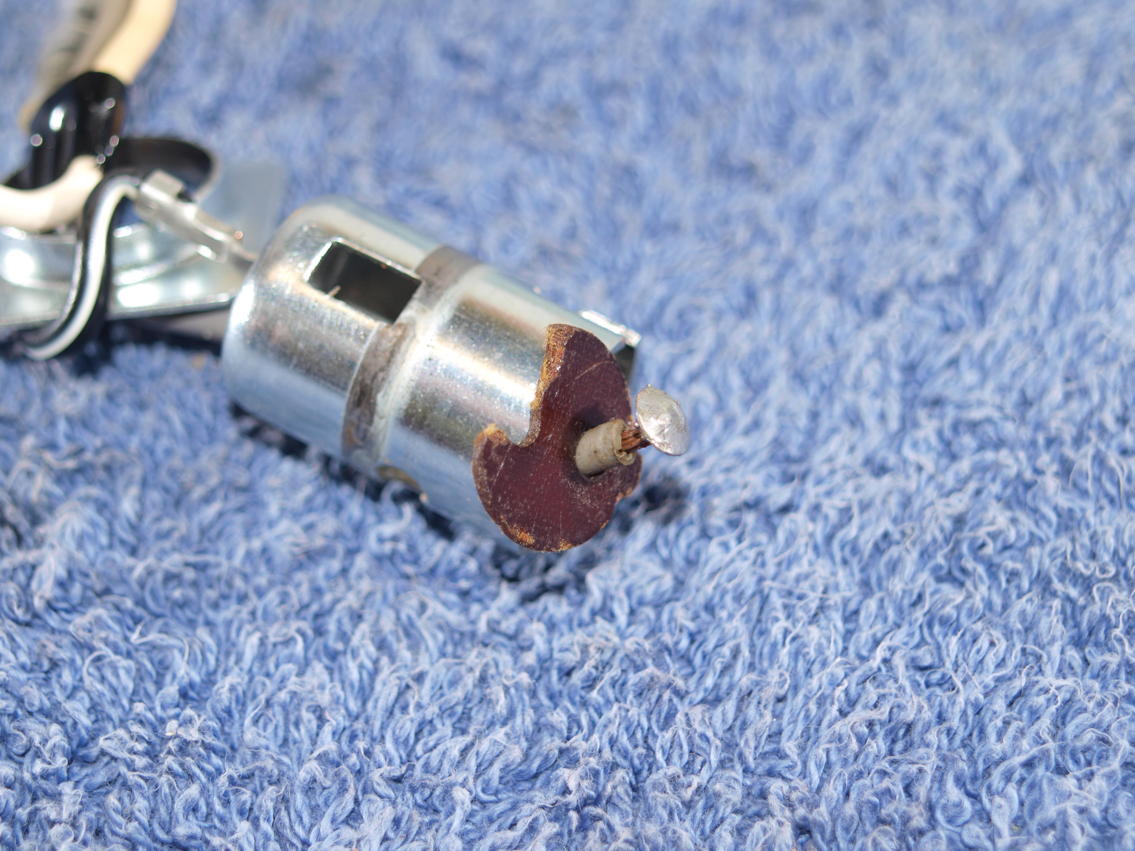
This is the rear light bulb holder and the cracked terminal connector plate, which isn’t going to be easily repaired with just a dab of superglue.
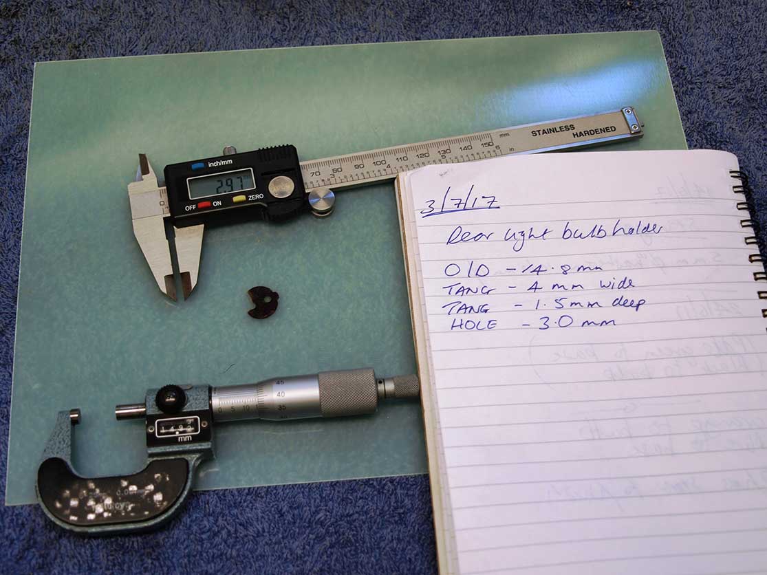
The cracked plate was made from a paper phenolic resin known as FR2 and used in cheap circuit boards. The modern equivalent is as woven glass fibre material known as FR4. Off eBay for a few pounds and ready to be used.
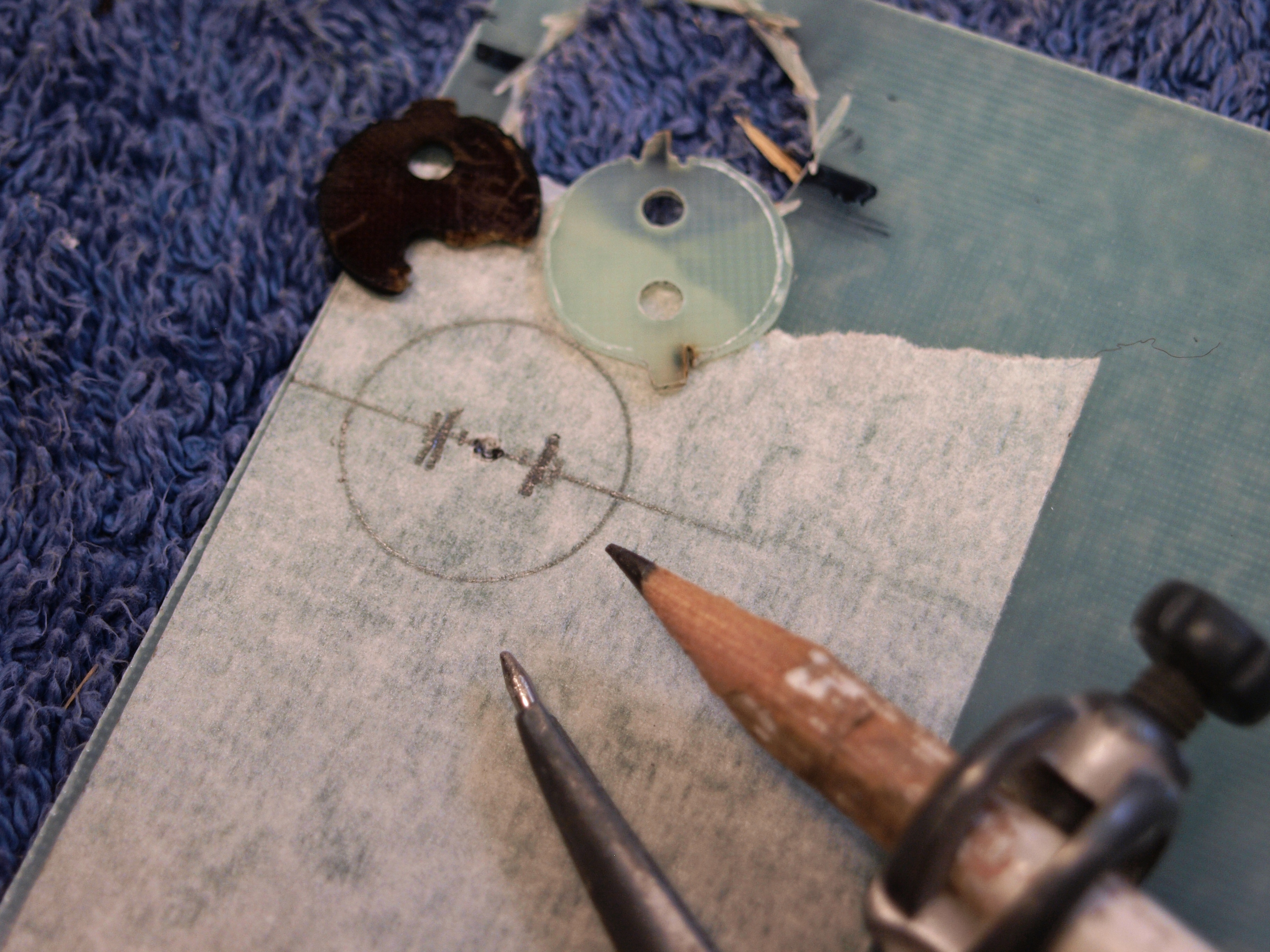
First off, a rough replica is made as a sighting shot to evaluate proof of concept. The second, more accurate, terminal connector plate is drawn up and drilled.
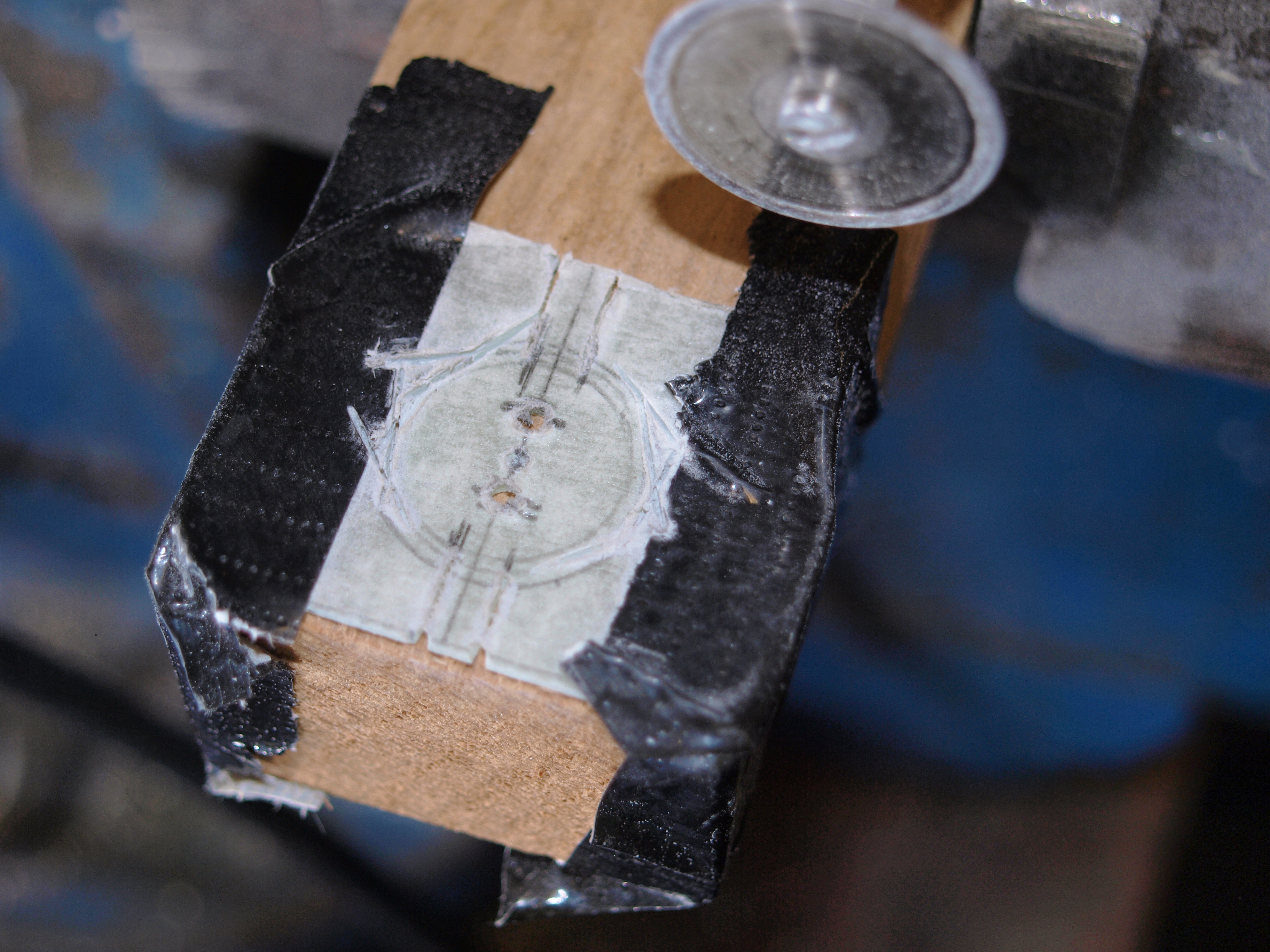
Cut approximately to shape with my trusty old Dremel the laminate is held in place with some strong duct tape ready to be tidied up.
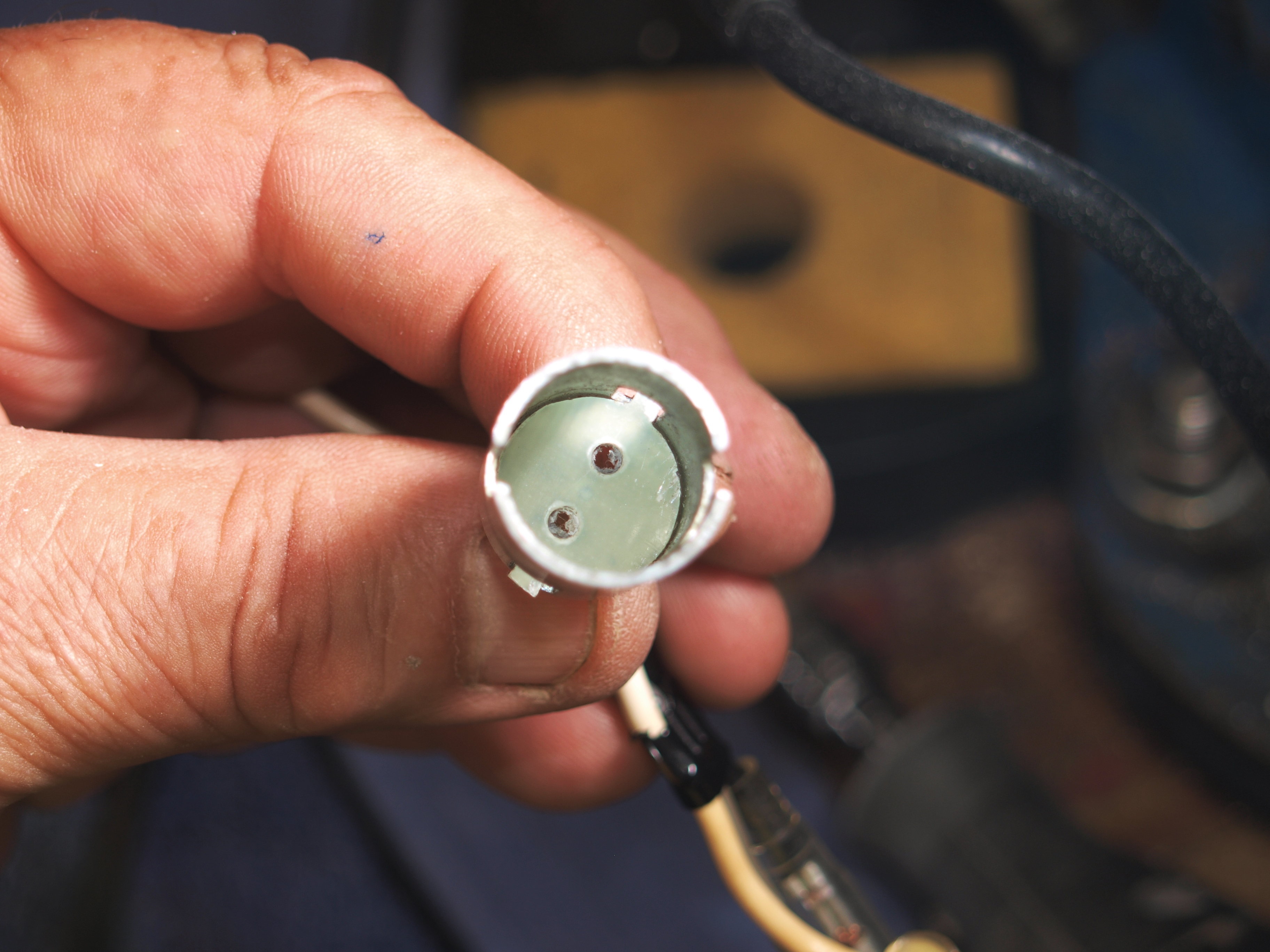
Following a session with some files, the new plate is dropped in the bulb holder for a trial fitting and fettled where necessary, so that it slides inside the bulb holder’s cut-outs.
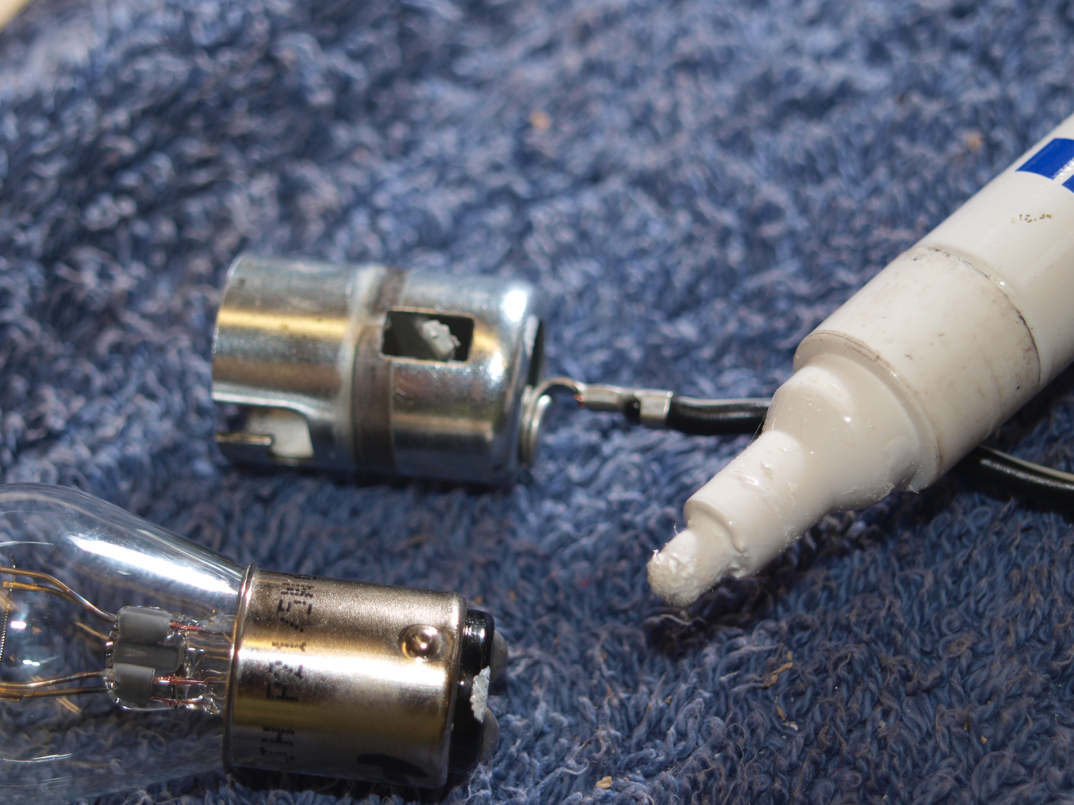
Easily overlooked but crucial, we need to know which terminal to connect to which element. A quick mug-up with the Stinger’s battery allows me to determine which one is the brake light and which is the rear light.
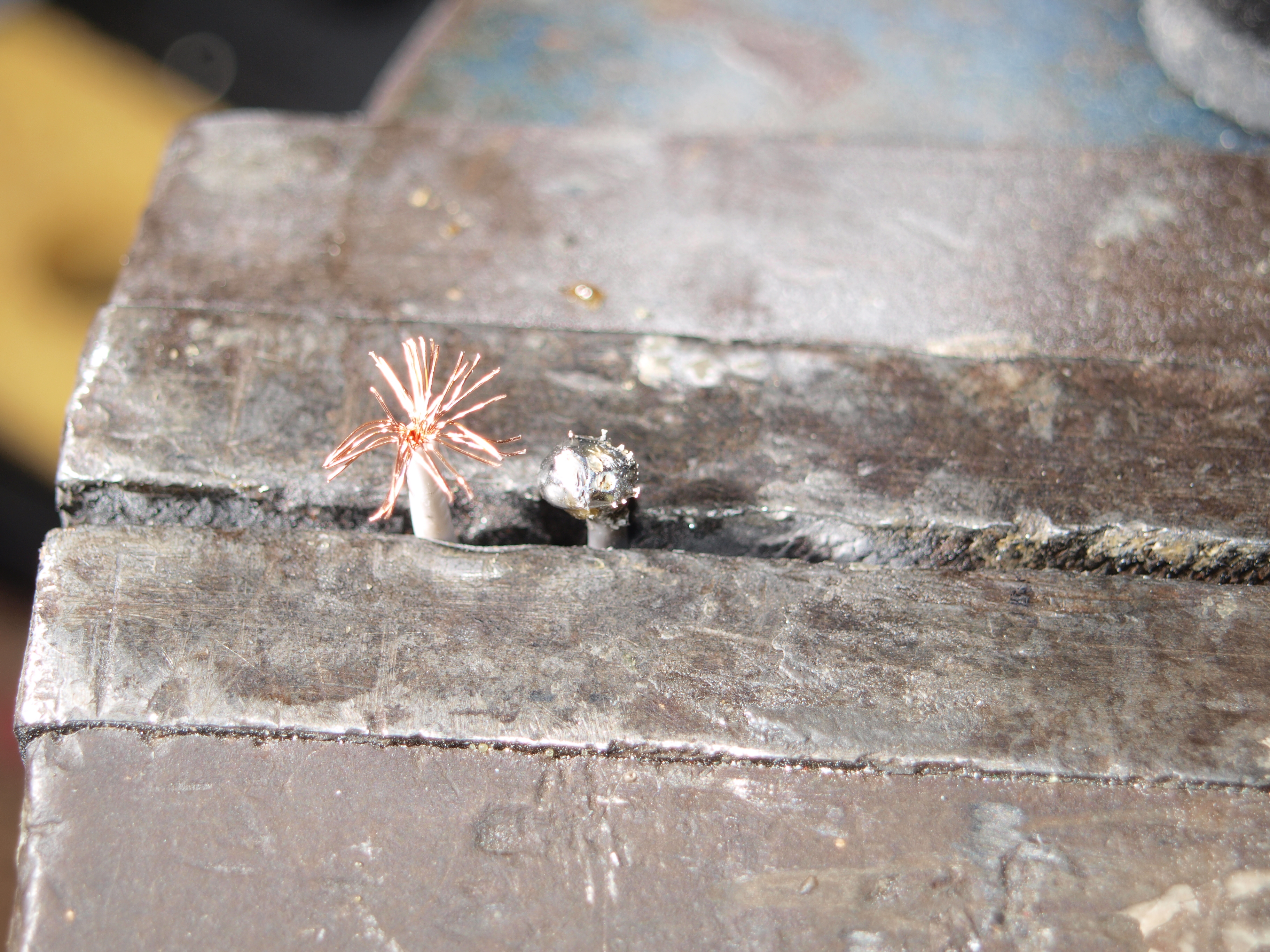
Two soldered terminals are now created on lengths of new wiring. These will be further fashioned with a fine file to be the points of contact with the bulb.
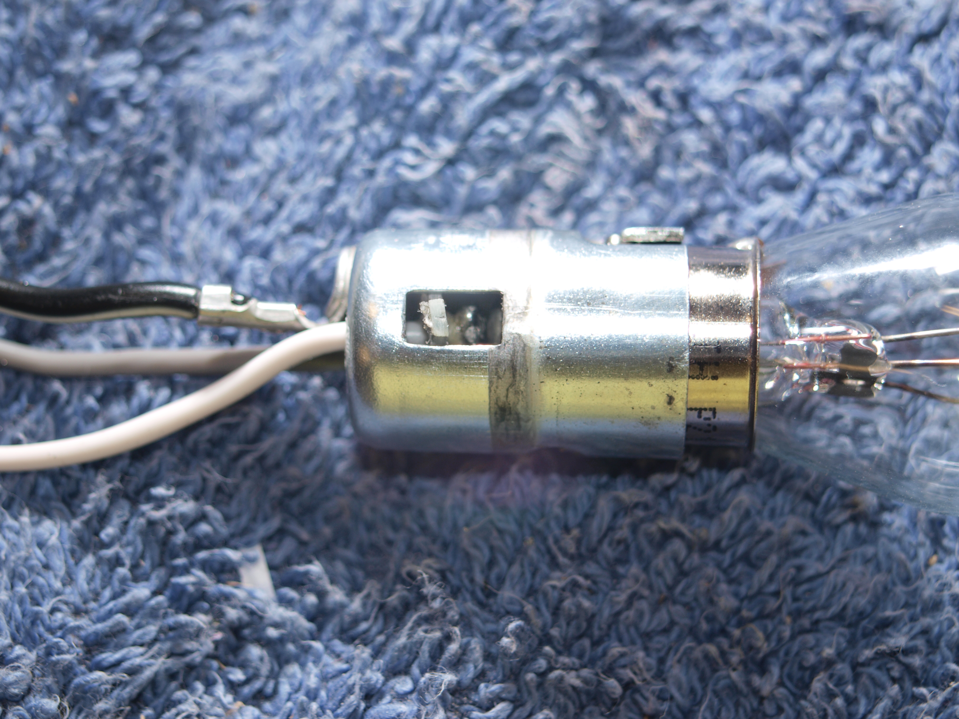
The bulb fits into the holder and via finger pressure and the multi-meter I’ve confirmed there’s continuity to both elements, hooray!
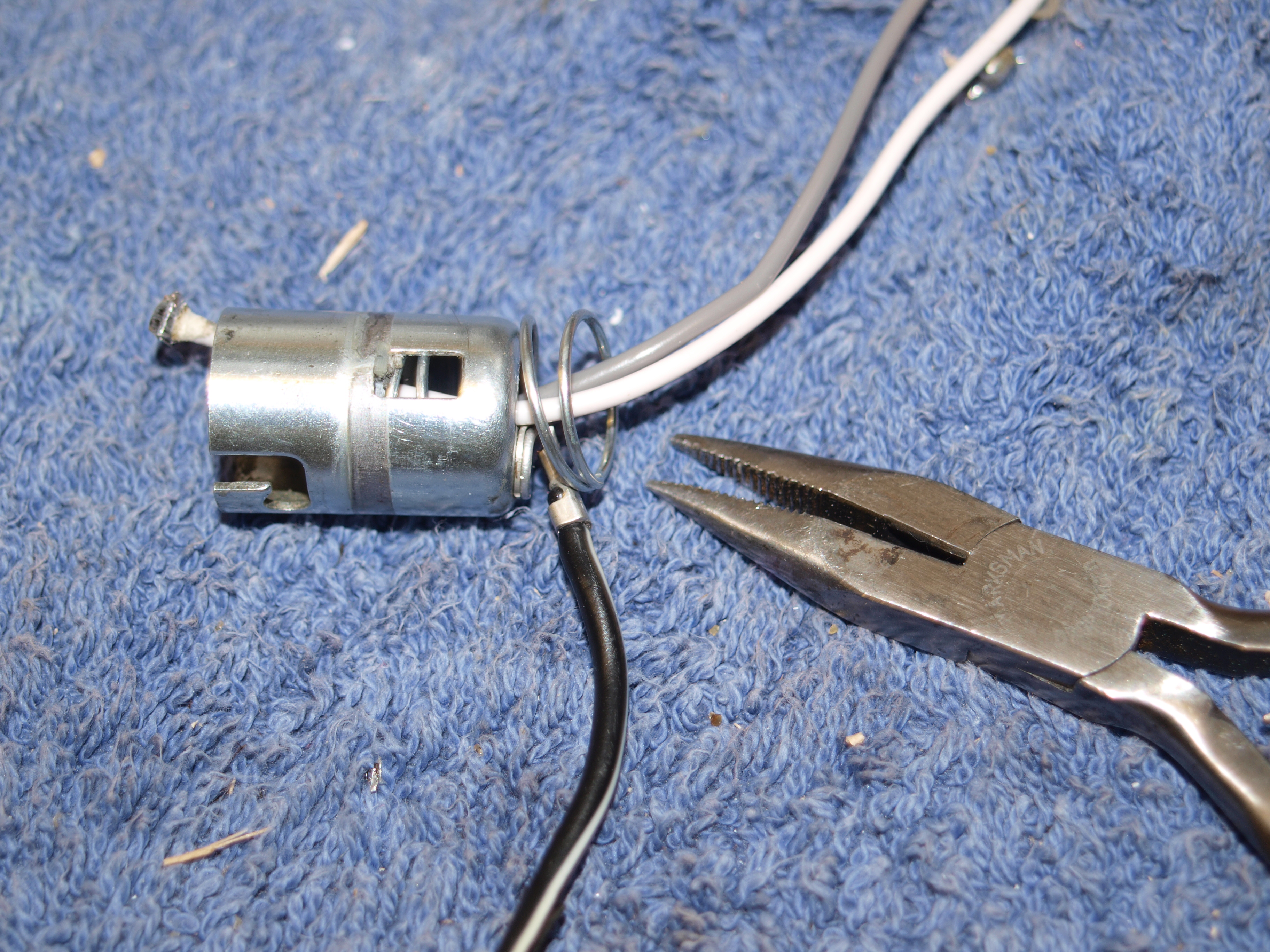
Frustrating and exacerbating, the spring is wound back into the bulb holder. I strongly doubt Suzuki’s suppliers’ faffed around like this but it’s the only option I have without small presses and the like.
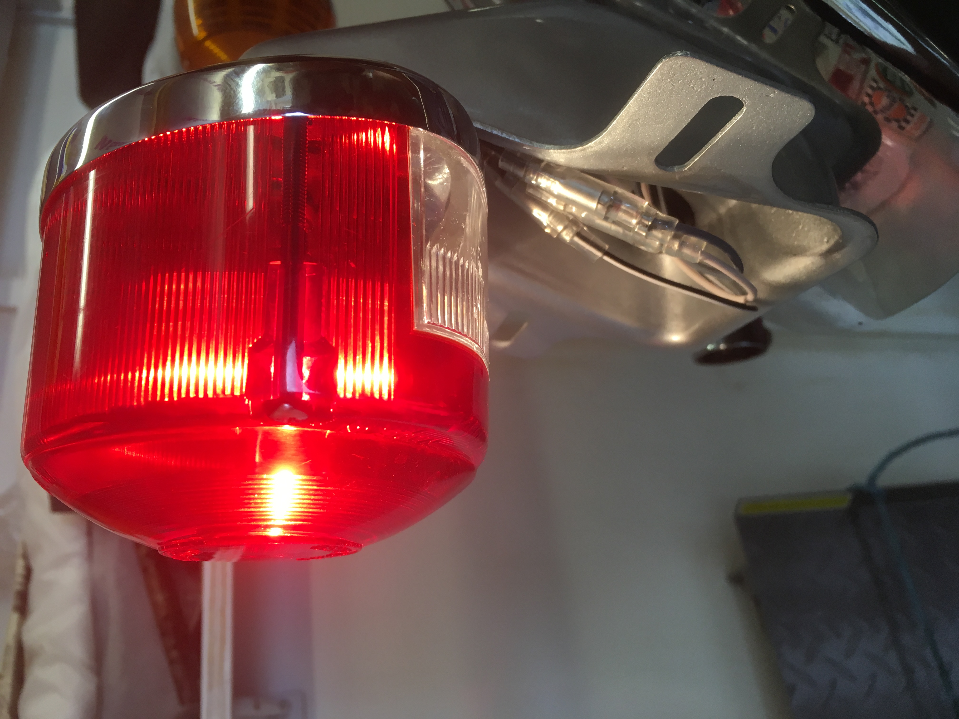
We are finished. Satan’s Stinger has a working rear light… Result!
So, finally I have the lighting systems of the Stinger sorted and to be honest it wasn’t as onerous as I thought it would be. Few of us classic fans are experts on electrics yet stuff like this is, actually, relatively simple. Grasp the fact, that in situations such as this, the power has to come into the bulb and out again and the idiot lights scenario was an easy win. After all, there’s a finite list of things to check; bulb, connectors, wires and terminals so it could only be one or more those four. With the rear light the fault was obvious but demanded some lateral thought to solve the problem. Not every electrical issue on an old bike needs to be nightmare to unravel. Fix one thing at a time and only then move onto the next.
For more technical advice, visit Motorcycle Workshop Guides: The Complete List.
To find out more about a classic bike policy from Footman James and to get an instant quote online, visit our Classic Bike Insurance page.
The information contained in this blog post is based on sources that we believe are reliable and should be understood as general information only. It is not intended to be taken as advice with respect to any specific or individual situation and cannot be relied upon as such.

COMMENT